
CMMC Data Flow Diagrams: An Ultimate Guide
This blog focuses on how organizations define those boundaries. We collaborated with KNC Strategic Services (KNCSS), an authorized third party assessor organization (C3PAO). They offered their own take on creating a data flow diagram.

The Cybersecurity Maturity Model Certification (CMMC) program protects federal information from unauthorized disclosure. Organizations will either self-assess or undergo a third party assessment of security requirements.
Level 1 is for organizations that handle Federal Contract Information (FCI).
Level 2 adds additional safeguarding requirements for protecting Controlled Unclassified Information (CUI). Organizations may have separate boundaries for processing FCI and CUI.
This blog focuses on how organizations define those boundaries. We collaborated with KNC Strategic Services (KNCSS), an authorized third party assessor organization (C3PAO). They offered their own take on creating a data flow diagram.
How does a Data Flow Diagram help identify the authorization boundary?
Creating a data flow diagram helps identify relevant system elements. KNCSS shared a data flow diagram they’ve used for their own certification assessment.
Creating data flow diagrams for FCI and CUI may identify different system elements. This may lead towards logical and physical segmentation to manage varying sensitivity levels.
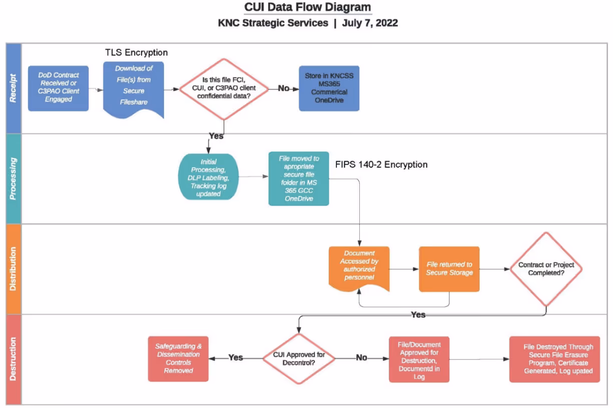
Receive
- What components make up the entry points for data flow?
- Identify relevant system components/elements.
Process
- What do we do with the information once it is in the system?
- Do we create derivative data based on FCI or CUI that we receive?
Distribute
- What components make up the exit points for data flow?
- Are there interconnections to another authorization boundary?
Destroy
- What is the process of destroying sensitive information?
- Identify relevant system components/elements.
What is an authorization boundary?
The National Institute of Standards and Technology (NIST) publishes information security standards.
Their Risk Management Framework (RMF) is a structured approach to securing information systems. The RMF defines an authorization boundary as a set of system elements under an organization's direct management.
A system is a set of interacting elements organized to achieve one or more stated purposes. System elements include technology elements, human elements, and physical or environmental elements. This matches the CMMC Scoping Guide, which references people, technology, and facilities.
The operational environment is the environment that influences the system's operation. For example, enabling systems provide but are not contained within the authorization boundary.
An enabling system may provide services or monitoring functionalities. Other systems outside the authorization boundary may interact with the system. Other systems may benefit from or have some general interaction with the system.
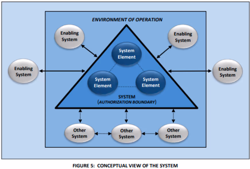
The authorization boundary may include certain parts of the environment of operation. For example, a facility protecting system elements may be within the authorization boundary.
Systems may also inherit controls from other systems with their own authorization boundaries. For example, inheriting physical protection controls from a cloud service provider (CSP).
The Department of Defense (DoD) recently clarified requirements around Cloud Service Offerings (CSOs).
CSOs utilized to handle CDI, must have a FedRAMP Moderate authorization or equivalent. The FedRAMP marketplace lists all FedRAMP Moderate authorizations. DoD defined equivalency as 100 percent compliance with the latest FedRAMP moderate baseline.
CSOs must achieve this through a third party assessment organization (3PAO) assessment. CSPs must also produce a supporting body of evidence (BoE). The BoE should includes the following:
- System Security Plan (SSP)
- Security Assessment Plan (SAP)
- Security Assessment Report (SAR)
- Shared Responsibility Matrix (SRM)
How does the authorization boundary affect self assessments and third-party assessments
The authorization boundary determines the allocation of security requirements to system elements. Organizations have the flexibility to establish their own authorization boundary for a system.
When defining the authorization boundary, consider elements within it that:
- Are generally under the same direct management
- Support the mission or business functions
- Have similar operating characteristics and security requirements
- Process, store, and transmit similar types of information
- Reside in the same environment of operation
Extensive authorization boundaries complicate the implementation of security requirements. Organizations may not need to deploy higher-impact controls across the entire organization. Creating isolation between systems allows for a more targeted implementation of security requirements.
How do you define a CMMC Level 1 authorization boundary?
The CMMC Scoping Guide provides guidance on defining assets within scope. Processing FCI may include components that access, enter, edit, generate, manipulate or print. Storing FCI may include electronic media, system component memory, or paper documents.
Transmitting FCI may include physical or digital transportation methods. Organizations should consider people, technology, and facilities that process, store, or transmit FCI.
Out of scope assets include any assets that do not process, store, or transmit FCI. Specialized assets are out of scope for Level 1 requirements as well.
This includes:
- Internet of Things devices (IoT)
- Industrial Internet of Things devices (IIoT)
- Operational Technology
- Government Furnished Equipment (GFE)
- Restricted Information Systems
- Test Equipment
How do you define a CMMC Level 2 authorization boundary?
The CMMC Level 2 Scoping Guide provides guidance on defining the assets within scope.
For Level 2, map organizational assets into one of five categories:
- CUI Assets - assets that process, store, or transmit CUI
- Security Protection Assets (SPA) - provide security functions to the assessment scope. SPA do not need to process, store, or transmit CUI
- Contractor Risk Managed Assets (CRMA) - are not intended to, process, store, or transmit CUI. Security policy, procedures, and practices in place to limit their access to CUI. They are not required to be physically or logically separated from CUI assets.
- Specialized Assets (SA) - can process, store, or transmit CUI but have limited security. Includes IoT, IIoT, OT, GFE, Restricted Information Systems, and Test Equipment.
- Out of Scope Assets - cannot process, store or transmit CUI and do not provide security protection. Includes classified assets, even if they contain applicable Controlled Unclassified Information.
The scope of system elements relevant to CUI may differ from the scope relevant to FCI. Completing the data flow diagram for both will identify relevant system components. Level 2 assessments include all categories listed above except out of scope assets.
The NIST SP 800-171 security requirements inform the inventory of security protection assets. Organizations may implement some security requirements manually or automate them using technical means.
Other security requirements are dependent on technical solutions to achieve (antivirus or MFA). Organizations should inventory the current security protection assets protecting the CUI assets. Using an applicability matrix may help identify any gaps in coverage.
An external service provider (ESP) may process, store or transmit CUI. ESPs may also provide security functions or capabilities to the authorization boundary. ESPs that process, store, or transmit CUI must meet the FedRAMP moderate requirements. ESPs that store security protection data must have a CMMC Level 2 Certification.
How to create a network diagram
A network diagram is a visual representation of the components within a system. The network diagram is the foundation for depicting the authorization boundary.
FedRAMP provides some insight into how to create an network diagram:
- Depict subnetting
- Depict location of DNS servers including:
- External authoritative services used to access the system
- Internal recursive servers used to access domains outside the boundary
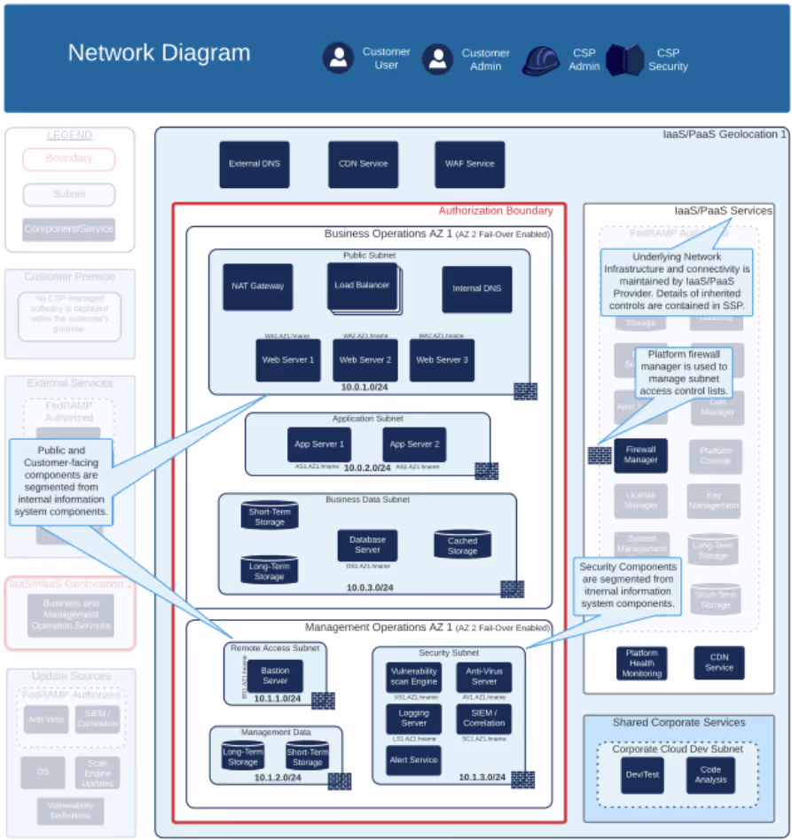
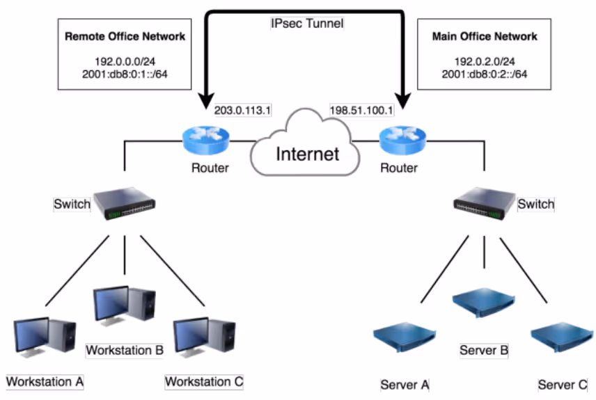
Although informative, the FedRAMP guidance sets a very high bar. NIST provides another notional depiction of a network diagram as seen below. This simplified diagram bears closer resemblance to the network diagram created by KNCSS.
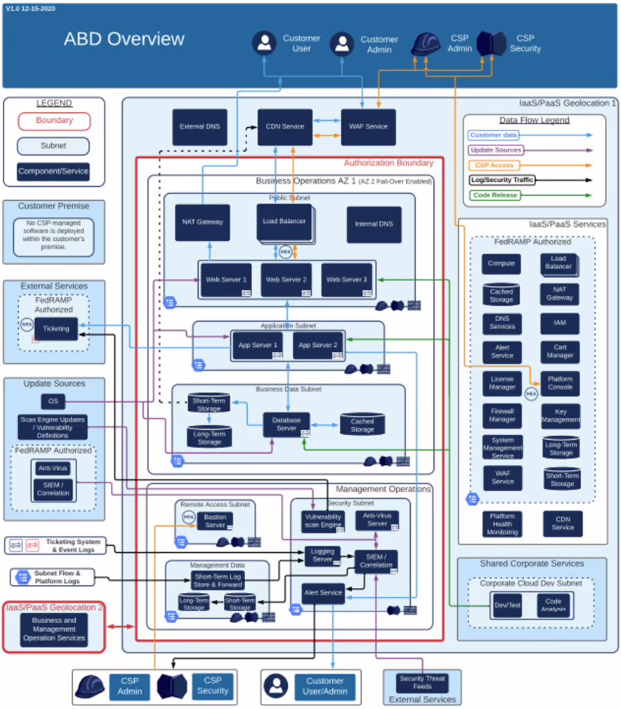
How to create an Authorization Boundary Diagram
An Authorization Boundary Diagram (ABD) is overlaid on the network diagram.
The FedRAMP Guidance provides some insights into how to create an ABD:
- Provide an easy-to-read diagram that includes a legend
- It should be readable without having to enlarge it
- Include a prominent RED border drawn around the authorization boundary
- Depict all ingress / egress points
- Depict services leveraged from underlying IaaS/PaaS/SaaS
- Identify any services that are not FedRAMP authorized
- Depict interconnected systems and external services, including shared services
- Identify any systems/services that are not FedRAMP authorized
- Depict every tool, service, or component mentioned in the SSP
- Identify all tools, services, or components as either external or internal
- Depict dev/test environment, alternate processing sites, and location of backups
- Include the associated connections and security mechanisms with these services
Conclusion
Implementing NIST SP 800-171 before identifying the data flow is like putting up a fence without knowing the property lines. The authorization boundary for FCI may differ from the CUI boundary.
Data flow diagrams help identify components that process, store, or transmit sensitive data. Data flow diagrams enable the creation of more relevant network diagrams. Network diagrams serve as the foundation for establishing an authorization boundary.
We recommend organizations review their proposed authorization boundaries with an authorized C3PAO. The earlier in the process, the better. The authorization boundary is the map that guides your implementation efforts. It helps prescribe where to implement technical requirements.
Don't wait until your certification assessment to have your authorization boundary vetted. Consider using KNCSS or any authorized C3PAO for this consultation.
Emphasize your product's unique features or benefits to differentiate it from competitors
In nec dictum adipiscing pharetra enim etiam scelerisque dolor purus ipsum egestas cursus vulputate arcu egestas ut eu sed mollis consectetur mattis pharetra curabitur et maecenas in mattis fames consectetur ipsum quis risus mauris aliquam ornare nisl purus at ipsum nulla accumsan consectetur vestibulum suspendisse aliquam condimentum scelerisque lacinia pellentesque vestibulum condimentum turpis ligula pharetra dictum sapien facilisis sapien at sagittis et cursus congue.
- Pharetra curabitur et maecenas in mattis fames consectetur ipsum quis risus.
- Justo urna nisi auctor consequat consectetur dolor lectus blandit.
- Eget egestas volutpat lacinia vestibulum vitae mattis hendrerit.
- Ornare elit odio tellus orci bibendum dictum id sem congue enim amet diam.
Incorporate statistics or specific numbers to highlight the effectiveness or popularity of your offering
Convallis pellentesque ullamcorper sapien sed tristique fermentum proin amet quam tincidunt feugiat vitae neque quisque odio ut pellentesque ac mauris eget lectus. Pretium arcu turpis lacus sapien sit at eu sapien duis magna nunc nibh nam non ut nibh ultrices ultrices elementum egestas enim nisl sed cursus pellentesque sit dignissim enim euismod sit et convallis sed pelis viverra quam at nisl sit pharetra enim nisl nec vestibulum posuere in volutpat sed blandit neque risus.
Use time-sensitive language to encourage immediate action, such as "Limited Time Offer
Feugiat vitae neque quisque odio ut pellentesque ac mauris eget lectus. Pretium arcu turpis lacus sapien sit at eu sapien duis magna nunc nibh nam non ut nibh ultrices ultrices elementum egestas enim nisl sed cursus pellentesque sit dignissim enim euismod sit et convallis sed pelis viverra quam at nisl sit pharetra enim nisl nec vestibulum posuere in volutpat sed blandit neque risus.
- Pharetra curabitur et maecenas in mattis fames consectetur ipsum quis risus.
- Justo urna nisi auctor consequat consectetur dolor lectus blandit.
- Eget egestas volutpat lacinia vestibulum vitae mattis hendrerit.
- Ornare elit odio tellus orci bibendum dictum id sem congue enim amet diam.
Address customer pain points directly by showing how your product solves their problems
Feugiat vitae neque quisque odio ut pellentesque ac mauris eget lectus. Pretium arcu turpis lacus sapien sit at eu sapien duis magna nunc nibh nam non ut nibh ultrices ultrices elementum egestas enim nisl sed cursus pellentesque sit dignissim enim euismod sit et convallis sed pelis viverra quam at nisl sit pharetra enim nisl nec vestibulum posuere in volutpat sed blandit neque risus.
Vel etiam vel amet aenean eget in habitasse nunc duis tellus sem turpis risus aliquam ac volutpat tellus eu faucibus ullamcorper.
Tailor titles to your ideal customer segment using phrases like "Designed for Busy Professionals
Sed pretium id nibh id sit felis vitae volutpat volutpat adipiscing at sodales neque lectus mi phasellus commodo at elit suspendisse ornare faucibus lectus purus viverra in nec aliquet commodo et sed sed nisi tempor mi pellentesque arcu viverra pretium duis enim vulputate dignissim etiam ultrices vitae neque urna proin nibh diam turpis augue lacus.